
This chapter discusses basic information about bridges and bridging operation. The chapter includes the following sections:
A bridge is a device that links two or more local area networks. The bridge accepts data frames from each connected network and then decides whether to forward each frame based on the medium access control (MAC) header contained in the frame. Bridges originally linked two or more homogeneous networks. The term homogeneous means that the connected networks use the same bridging method and media types. Examples of these would be networks supporting the source routing bridging method only or transparent bridging algorithm only (these methods will be explained later).
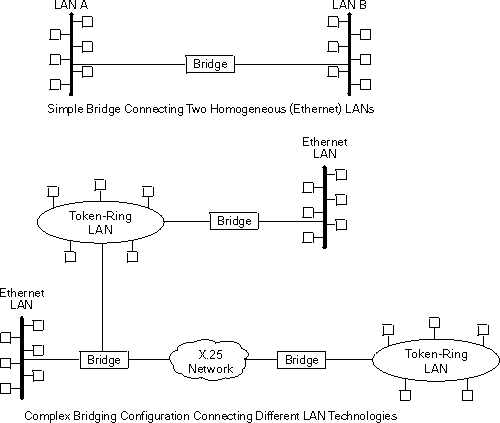
Current bridges also allow communication between non-homogeneous networks. Non-homogeneous refers to networks that can mix different bridging methods and can also offer more configuration options. Figure 1 illustrates examples of simple and complex bridging configurations.
Figure 1. Simple and Complex Bridging Configuration
 |
The 2212 can perform both bridging and routing. Protocol filtering is the process that determines whether the incoming data is routed or bridged.
When processing an incoming data packet, the following actions occur:
Table 1 shows how the "Bridge or Route?" question is answered
based on the destination address contents.
Table 1. Route/Bridge Decision Table
| If the Destination MAC Address in the Received Frame Contains: | The Bridge takes this action: |
|---|---|
| Bridge Address | The bridge passes the frame to the configured protocol that routes the frame. |
| Multicast or Broadcast Address | If there is a configured protocol in the frame, the frame is routed. Otherwise, the frame is bridged. |
| Unicast | The frame is bridged. |
For IP, IPX, and AppleTalk, the following rules apply for routing or bridging over a specific interface:
Connecting at Layer 3 with a router enables connectivity and path selection between end stations located in distant geographical areas. Using routing protocols, you can select the best path for connecting distant and diverse LANs. Because of the variety of network and subnetwork configuration options available to you in large networks, connecting LANs through the Network Layer is usually the preferred method. Network-layer protocols have also proven to be very efficient in moving information in large and diverse network configurations.
Connecting at Layer 2 with a bridge provides connectivity across a physical link. This connection is essentially "transparent" to the host connected on the network.
| Note: | Source routing bridges are not considered completely "transparent." See "Bridging Methods" for more information on source routing and transparent bridges. |
The Link Layer maintains physical addressing schemes (versus logical at Layer 3), line discipline, topology reporting, error notification, flow control, and ordered delivery of data frames. Isolation from upper-layer protocols is one of the advantages of bridging. Because bridges function at the Link Layer, they are not concerned with looking at the protocol information that occurs at the upper layers. This provides for lower processing overhead and fast communication of network layer protocol traffic. Because bridges are not concerned with Layer 3 information, they can also forward different types of protocol traffic (for example, IP or IPX) between two or more networks (as routers do).
Bridges can also filter frames based on Layer 2 fields. This means that the bridge can be configured to accept and forward only frames of a certain type or ones that originate from a particular network. This ability to configure filters is very useful for maintaining effective traffic flow.
Bridges are advantageous when dividing large networks into manageable segments. The advantages of bridging in large networks can be summed up as follows:
Internetworking devices such as bridges and routers have similar functions in that they connect network segments. However, each device uses a different method to establish and maintain the LAN-to-LAN connections. Routers connect LANs at Layer 3 (Network Layer) of the OSI model while bridges connect LANs at Layer 2 (Link Layer).
The following sections describe specific types of bridges and how they can be classified by their hardware and software capabilities.
Simple bridges consist of two or more linked network interfaces connecting local area networks ( Figure 1). Bridges interconnect separate local area networks (LANs) by relaying data frames between the separate MAC (medium access control) entities of the bridged LANs.
The main functions of a simple bridge can be summarized as follows:
Most simple bridges contain routing addressing and routing intelligence. At a minimum, the bridge must know which addresses are on each connected network so that it can know which frames to pass on.
Complex bridges carry out more sophisticated functions than simple bridges. These functions may include the bridge maintaining status information on the other bridges. This information includes the communication path cost as well as the number of hops required to reach each connected network. Periodic exchanges of information between bridges update all bridge information. These types of exchanges enable dynamic routing between bridges.
Complex bridges can also modify frames and recognize and transmit packets from different LAN technologies (for example, Token-Ring, and Ethernet). In this case the bridge is sometimes referred to as a translational bridge.
The adaptive source routing transparent (ASRT) bridge is the 2212's implementation of bridge technology. The ASRT Bridge is a collection of software components capable of several of the bridging options just described and more. All of these functions are explained in greater detail later in this chapter.
Local bridges provide connections among several LAN segments in the same geographical area. An example of this would be a bridge used to connect the various LANs located in your company's main headquarters.
Remote bridges connect multiple LAN segments in different geographical areas. An example of this would be bridges used to connect the LANs located in your company's main headquarters to LANs in other branch offices around the country. Because of the geographical differences, this configuration moves from a local area network configuration to a wide area network (WAN) configuration.
Remote bridges can differ from local bridges in several ways. One major difference is in the speed at which data is transmitted. WAN connections may be slower than LAN connections. This difference in speed can be significant when running time-sensitive applications. Another difference is in the physical way in which remote and local bridges are connected to LANs. In local bridges, the connections are made through local cabling media (for example, Ethernet, Thinet). Remote bridge connections are made over the serial lines.
According to the IEEE 802 LAN standard, all station addresses are specified at the MAC level. At the Logical Link Control (LLC) level, only SAP (Service Access Point) addresses are designated. Accordingly, the MAC level is the level at which the bridge functions. The following examples explain how bridging functions proceed at this level.
Figure 2 shows a two-port bridge model connecting end stations on two separate LANs. In this example, the local bridge connects LANs with identical LLC and MAC layers (that is, two token-ring LANs). Conceptually, you can think of the bridge as a data link relay that forwards frames between the media access control (MAC) sublayers and physical channels of the attached LANs, thus providing data link connectivity between them.
To summarize the bridging process, the bridge captures MAC frames whose destination addresses are not on the local LAN (that is, the LAN connected to the interface receiving the transmitted frame). It then forwards them to the appropriate destination LAN. Throughout this process, there is a dialogue between the peer LLC entities in the two end-stations. Architecturally, the bridge need not contain an LLC layer because the function of the LLC layer is to merely relay MAC frames that come from upper levels of the OSI model.
Figure 2. Two-Port Bridge Connecting Two LANs
 |
Figure 3 shows a pair of bridges connected over a serial link. These remote bridges connect LANs with identical LLC and MAC layers (that is, two token-ring LANs).
To summarize, the bridge captures a MAC frame whose destination address is not on the local LAN and then sends it to the appropriate destination LAN via the bridge on that LAN. Throughout this process, there is a dialogue between the peer LLC entities in the two end stations. Architecturally, the bridge need not contain an LLC layer because the function of the LLC layer is to merely relay MAC frames that come from upper levels of the OSI model.
Figure 3. Bridging Over a Point-to-Point Link
 |
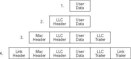
Data is encapsulated as the bridges communicate data over the serial link. Figure 4 illustrates the encapsulation process.
Figure 4. Data Encapsulation Over a Point-to-Point Link
 |
Encapsulation proceeds as follows:
When the data frame reaches Bridge B (the target bridge), the link fields are stripped off and Bridge B transmits the original, unchanged MAC frame to its destination, end station B.
As mentioned, bridges interconnect LANs by relaying data frames, specifically MAC frames, between the separate MAC entities of the bridged LANs. MAC frames provide the necessary "Where?" information for frame forwarding in the form of source and destination addresses. This information is essential for the successful transmission and reception of data.
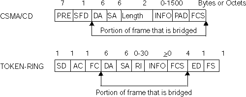
IEEE 802 supports three types of MAC frames: CSMA/CD (802.3), token bus (802.4), and token-ring (802.5). Figure 5 shows the MAC frame formats supported by the bridge. The specific frames are detailed in the following section.
| Note: | A separate frame format is used at the LLC level. This frame is then embedded in the appropriate MAC frame. |
Figure 5. Examples of MAC Frame Formats
 |
The following information describes each of the fields found in CSMA/CD (Ethernet) MAC frames:
The portion of the frame that is actually bridged consists of the following fields:
The following information describes each of the fields in token-ring MAC frames:
The portion of the frame that is actually bridged consists of the following fields:
This field is explained in more detail in "Source Route Bridging (SRB)".
Finally, the End Delimiter (ED) contains the error detection (E) bit, and the intermediate frame (I) bit. The I bit indicates that this is not the final frame of a multiple frame transmission. The Frame Status (FS) contains the address recognized (A) and frame copied (C) bits.